odop
Open Design Optimization Platform (ODOP) - Coil spring design app; mechanical springs; compression spring, extension spring, torsion spring
Torsion Spring Design Type

The Torsion Spring design type is a full-featured mathematical model enabling the engineering design of round wire helical coil torsion springs.
This section presents material unique to the Torsion Spring design type. The more general material available at Spring Design Topics provides important supplemental information.
On this page:
- Torsion spring variable names on Moment-Deflection diagram
- Torsion spring Moment-Deflection point names
- Torsion spring dimensions
- Independent Variable names
- Dependent Variable names
- Calculation Input names
- Values in reports
- Torsion spring end types
- Allowable stress values
- Allowable stress update
- Related topics
Torsion spring variable names on Moment-Deflection diagram
             |                /
     M_2 ----|---------------/
             |              /:
       M     |             / :
             |            /  :        ODOP:Spring
       O     |           /   :          Names
             |          /    :
       M     |         /     :          Torsion
             |        /      :          spring
       E     |       /       :
             |      /        :
    M_1 -----|-----/         :
             |    /:         :
       N     |   / :<------->:------- Stroke
             |  /  :         :
       T     | /   :         :
             |/____:_________:_________
        L_Free     :         :
                  L_1       L_2
             Deflect_1     Deflect_2

             D E F L E C T I O N
Torsion spring Moment-Deflection point names
The torsion spring moment-deflection points and associated names are:
| moment (torque) | deflection | length | outside diameter | inside diameter | |
|---|---|---|---|---|---|
| free: | L_Body | OD_Free | ID_Free | ||
| point 1: | M_1 | Deflect_1 | L_1 | ||
| point 2: | M_2 | Deflect_2 | L_2 | ||
| max safe: |
| stress | factor of safety | |
|---|---|---|
| free: | ||
| point 1: | Stress_1 | |
| point 2: | Stress_2 | FS_2 |
| max safe: |
point 1 = minimum operating load point 2 = maximum operating load
Torsion spring dimensions
The following diagram may be of some assistance in interpreting the names associated with various dimensions of a torsion spring.

Independent Variable names:
| Name | Description | |
|---|---|---|
| Wire_Dia | wire diameter | |
| OD_Free | outside diameter in the free condition | |
| Coils_T | total number of coils, including inactive coils | |
| M_1 | load (moment) at point 1 (minimum operating load) | |
| M_2 | load (moment) at point 2 (maximum operating load) | |
| Coil_Spacing | extra space between each coil |
Dependent Variable names:
| Name | Description | |
|---|---|---|
| Mean_Dia | mean diameter of spring coil in free condition; (OD_free + ID_Free)/2 | |
| ID_Free | inside diameter in free condition | |
| Coils_A | number of active coils (turns; includes arm deflection) | |
| Rate | spring constant - moment per unit deflection | |
| Deflect_1 | deflection caused by M_1 | |
| Deflect_2 | deflection caused by M_2 | |
| L_Body | length of body in free condition (without ends) | |
| L_1 | spring body length at minimum operating load (M_1) | |
| L_2 | spring body length at maximum operating load (M_2) | |
| End_Angle_Free | relative angle between arms in free condition | |
| Stroke | angular displacement from point 1 to point 2 | |
| Weight | weight of spring; wire density * wire volume | |
| Spring_Index | spring index; the ratio: Mean_Dia/Wire_Dia | |
| End_Deflect_All | End deflection allowance (equivalent coils); calculated from L_End_1 + L_End_2 | |
| Stress_1 | bending stress at point 1 | |
| Stress_2 | bending stress at point 2 | |
| FS_2 | static factor of safety at point 2; The ratio of allowable stress at point 2 to the calculated stress induced by the load at point 2 (Stress_Lim_Bnd_Stat/Stress_2). | |
| FS_Cycle_Life | factor of safety based on the Soderberg endurance limit calculation. This figure uses the allowable endurance stress (Stress_Lim_Bnd_Endur) to include fatigue considerations. Refer to additional discussion in the Cycle_Life topic. | |
| Cycle_Life | expected cycle life based on a calculation using the "modified Goodman method". This value is approximate. Refer to additional discussion in the Cycle_Life topic. | |
| %_Safe_Deflect | the percentage of available deflection consumed at load point 2 | |
| Force_Arm_2 | Force produced at distance of Arm_2; See: Torsion spring dimensions | |
| Energy | change in elastic potential energy between point 1 and point 2 |
For additional information: Cycle_Life
Calculation Input names
| Name | Description | |
|---|---|---|
| Spring_Type | character string used only as a label | |
| Prop_Calc_Method | Property Calculation Method controls how material properties and allowable stresses are determined. See also: Materials. | |
| 1 - indicates values come from materials table; allowable stresses will be calculated as a function of Wire_Dia. | ||
| 2 - indicates tensile and allowable % are supplied by the user; allowable stresses are calculated. | ||
| 3 - indicates allowable stresses are supplied directly by the user. | ||
| Material_Type | selects an entry in the material table. Is used to determine allowable stresses when Prop_Calc_Method is 1. Otherwise is ignored. | |
| ASTM/Fed-Spec | character string used only as a label to further identify the origin of material property data | |
| Process | character string used to identify the manufacturing process. It is normally controlled by the material selected from the material table. Values are usually Cold_Coiled or Hot_Wound. See also: Hot_Factor_Kh (below). | |
| Heat_Treat | Selects heat treatment process. Controls use of Kb - stress correction factor | |
| Life_Category | This value reflects the user's input about shot peening and required cycle life. It is input to the calculation of FS_CycleLife. See also: Cycle_Life | |
| Density | wire density; weight per unit volume | |
| Elastic_Modulus | Modulus of Elasticity (E) (a.k.a. Young's Modulus) | |
| Hot_Factor_Kh | empirical correction factor applied to hot wound modulus | |
| Tensile | tensile strength | |
| %_Ten_Bnd_Endur | allowable fraction of tensile strength for bending endurance (cyclic load); See also: Cycle_Life | |
| %_Ten_Bnd_Stat | allowable fraction of tensile strength for bending static load | |
| Stress_Lim_Bnd_Endur | allowable stress limit; cyclic application (bending) | |
| Stress_Lim_Bnd_Stat | allowable stress limit; static application (bending) | |
| End_Type | This selection indicates end configuration: Tangent ends versus User Specified ends.. See also: Torsion spring end types | |
| Arm_1, etc. | See: Torsion spring end types |
For additional information:
Values in reports
Other values calculated and displayed in the Reports include:
| Name | Description | |
|---|---|---|
| Wire Length | total length of wire required to manufacture the spring, not including any waste | |
| Safe Load | The load supported by the spring at maximum allowable stress (Stress_Lim_Bnd_Stat). | |
| Pitch | distance between the wire centers of adjacent coils, measured in the free state (Wire_Dia + Coil_Spacing) | |
| Weight/1000 | weight of 1,000 springs | |
| Stress Ratio | ratio of minimum stress to maximum stress (Stress_1/Stress_2) | |
| Kb | stress correction factor; (see: Heat_Treat above) | |
| Helix Angle | angle, in degrees, of the spring helix relative to a perpendicular to the spring axis |
End Types
For torsion springs, the Calculation Input End_Type has the following possible values:
     Torsion

1    Tangent
2    User_Specified
In the current version of ODOP:Spring, no calculations depend on these End_Type settings. They are for display only.
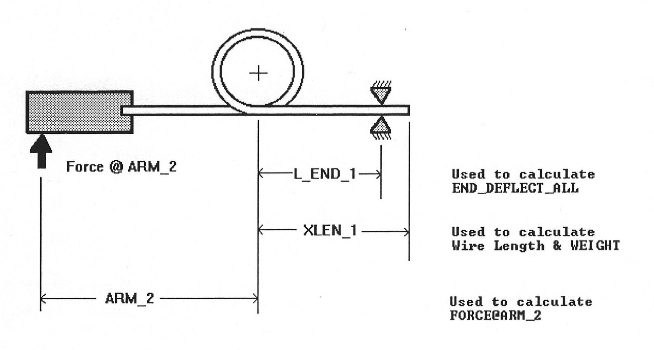
Separately, the values of Arm_1, Arm_2, L_End_1, L_End_2, XLen_1 and XLen_2 are available to describe end conditions. This diagram may be helpful.

Allowable Stress Values: An Overview
This section introduces the basics of selecting allowable stress values. More detail is available in Materials and Advanced Spring Operations.
The coils of compression and extension springs are subjected to torsion (twisting). The related Calculation Inputs include:
- Torsion_Modulus (G): Also called shear modulus or modulus of rigidity
- %_Tensile_Stat: allowable fraction of tensile strength for torsion static load
- %_Tensile_Endur: allowable fraction of tensile strength for torsion endurance (cyclic load)
In torsion springs, the coils experience bending. The related Calculation Inputs include:
- Elastic_Modulus (E): Also known as the modulus of elasticity or Young's modulus
- %_Ten_Bnd_Stat: allowable fraction of tensile strength for bending static load
- %_Ten_Bnd_Endur: allowable fraction of tensile strength for bending endurance (cyclic load)
The selection of these values is controlled by the Calculation Input Prop_Calc_Method.
- Prop_Calc_Method = 1, the values above are determined by ODOP:Spring's internal materials table.
- Prop_Calc_Method = 2, the values above are determined by user input.
- Prop_Calc_Method = 3, stress limits and modulus values are directly determined by user input.
When using ODOP:Spring's internal materials table (Prop_Calc_Method = 1) the tensile strength values (Calculation Input Tensile) change as a function of wire diameter. When Prop_Calc_Method = 2 or Prop_Calc_Method = 3, the Tensile value is determined by user input.
The Dependent Variable Cycle_Life is determined by the Modified Goodman calculation. It is available only when using ODOP:Spring's internal materials table (Prop_Calc_Method = 1) and is is not influenced by the value of the Calculation Input Life_Category.
The Dependent Variable FS_Cycle_Life is determined by the Soderberg calculation. It is available for all values of Prop_Calc_Method and uses the value of the Calculation Input Life_Category as a primary input. For more detail, see: Cycle_Life.
Allowable Stress Update
The latest version of ODOP:Spring introduces updated default values in its internal materials table, allowing for higher stress levels in torsion springs compared to earlier versions. These changes make it possible for higher-stress designs to be considered "feasible." As a result:
- The Search feature now considers less conservative (more highly stressed) designs as feasible.
- Designs may also display longer cycle life and/or reduced weight compared to previous versions.
If you open a torsion spring design created in a previous version of ODOP:Spring using the current version, you might notice:
- Increased Factor of Safety (FS): The updated internal materials table can result in higher FS values.
- Longer cycle life: Expect improvements in estimated cycle life for affected designs.
Note that these changes apply only to torsion spring designs that use the internal materials table (Prop_Calc_Method = 1).
In some cases, designs marked as "FEASIBLE" in older versions might now be flagged as "NOT FEASIBLE". This usually happens if the FS_2 MAX constraint is violated. To resolve this, Try increasing the value of FS_2 MAX. For example, raise it from 1.6 to 1.8 (or higher).
When you open an older design in the new version of ODOP:Spring, an informational message will appear. To prevent this message from showing up again, simply re-save the design in the current version.
For additional information, please contact customer support.
Related topics